|
1. OSST Series Galvanometer Optical Scanners
|
Part number |
OSST8162 |
OSST8161 |
OSST8062 |
|
Optical apertures supported, two-axis |
�5mm
|
�10mm
|
�12mm
|
|
Response time |
0.2ms at 5mm beam |
0.3ms
at 10mm beam |
0.6ms at 12mm beam |
|
Max
mechanical rotation angle |
�20�-30 |
�20� |
�20� |
|
Linearity |
99.9%, over �20� |
99.9%,
over �20� |
99.9%, over �20� |
|
Average current |
0.9A |
0.9A |
1.5A |
|
Peak current |
5A
|
5A |
10A
|
|
Coil resistance |
3Ω�10% |
1.8Ω�10%
|
2Ω�10% |
|
Coil inductance |
180μH �10% |
280μH �10%
|
260μH �10% |
|
Operation temp |
0℃-40℃
|
0℃-40℃ |
0℃-40℃ |
|
Weight |
80g
|
105g |
180g |
|
Dimension |
f18x33+f30x20mm |
f18X33+f22x16mm |
f22x47+f35x21mm |
|
Axis diameter |
2mm |
3mm |
4mm |
|
Application |
Laser show, stage lighting |
Super speed fly marking |
Laser marking, rapid prototype, trimming, radar etc.
|
|
Part number |
OSST2238 |
OSST8061 |
OSST3808 |
|
Optical apertures supported, two-axis |
�12mm
|
�20mm
|
�32mm
|
|
Response time |
0.4ms at 12mm beam |
0.7ms at 20mm beam |
1ms at 32mm beam |
|
Max
mechanical rotation angle |
�20� |
�20� |
�20� |
|
Linearity |
99.9% over �20� |
99.9% over �20� |
99.9% over �20� |
|
Average current |
1.5A |
2A
|
2.2A |
|
Peak current |
10A |
15A
|
10A |
|
Coil resistance |
1.4Ω�10% |
2.1Ω�10% |
2Ω�10% |
|
Coil inductance |
420μH �10% |
360μH �10% |
260μH �10% |
|
Operation temp |
0℃-40℃ |
0℃-40℃ |
0℃-40℃ |
|
Weight |
180g |
210g |
520g |
|
Dimension |
f22x47+f35x21mm |
f28x57+f39x21mm |
f39X72+f35x21mm |
|
Axis diameter |
4mm |
5mm |
7mm |
|
Application |
High speed fly marking, high speed marking. |
Precise marking, prototype, trimming, radar. |
Precise marking, prototype, trimming, radar. |
OSST8061
2.
OSSL Series
Galvanometer Optical Scanners
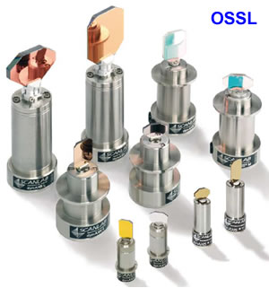
OSSL series galvanometer scanners are high-performance
rotary motors for optical applications. They consist of a motor section
based on moving magnet technology and a high-precision position
detector. The primary area of application is the fast and precise
positioning of mirrors for the deflection of laser beams.
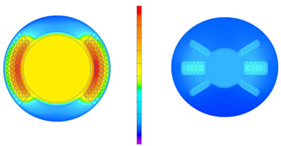
The exceptional dynamics OSSL Series scanners are the
result of years of experience in developing and manufacturing scanners,
scan systems and scan solutions for industrial use. The motor section of
each OSSL series is ideally matched to the inertial load presented by
the mirror. The optimized rotor design is largely responsible for the
favorable dynamic properties and resonance characteristics. Axially
pre-loaded precision ball bearings guarantee a backlash-free rotor
assembly with high stiffness and low friction. Special attention has
been paid to long bearing lifetimes.
The optical position detector system is characterized by
high resolution, as well as good repeatability and drift values. The
scanners are equipped with heaters and temperature sensors. This allows
temperature stabilization for further enhancing long-term stability,
even under fluctuating ambient conditions.
We provide all OSSL series scanners with suitable mirrors
and mirror coatings for all typical laser wavelengths. In addition to
very good reflection properties, the mirrors are also optimized with
respect to inertial load, stiffness and flatness. The high quality of
OSSL Series galvanometer scanners enables error-free operation in
long-term and continuous use. Comprehensive measurements on custom test
benches assure that the highest level of quality is continuously
maintained.
Mounting
The rotationally symmetrical flange facilitates mounting.
The scanner housing must be electrically insulated from the machine
structure. Mirror stops are already integrated into the scanners. The
mirror is directly bonded to the scanner�s shaft.
OSSL Series Galvanometer Scanners Specifications
|
Part number |
OSSL-XS |
OSSL-T |
OSSL-S |
OSSL-M |
OSSL-L |
|
Rotor inertia |
0.028 g�cm2 |
0.125 g�cm2 |
0.34 g�cm2 |
1.2 g�cm2 |
5.1 g�cm2 |
|
Torque constant |
2.3 N�mm/A |
5.3 N�mm/A |
7.5 N�mm/A |
15 N�mm/A |
24 N�mm/A |
|
Coil resistance |
3.9 Ω |
2.8 Ω |
2.7 Ω |
2.2 Ω |
0.85 Ω |
|
Coil inductance |
90μH |
145
μH |
165
μH |
275
μH |
300
μH |
|
Max. RMS current
(max. case temp. 50�C) |
1.8 A |
2.2 A |
2.5 A |
3.5 A |
5 A |
|
Peak current |
6 A |
10 A |
10 A |
10 A |
15 A |
|
Weight With cable |
49 g |
72 g |
263 g |
340 g |
425 g |
|
Weight Without cable |
23 g |
46 g |
- |
- |
- |
|
Connector |
SD-9 socket |
SD-9 socket |
SD-15 socket |
SD-15 socket |
SD-15 socket |
|
Inertial Load recommended |
0.02 g�cm2 |
0.1 g�cm2 |
0.35 g�cm2 |
1.2 g�cm2 |
8 g�cm2 |
|
Inertial Load maximum |
0.05 g�cm2 |
0.5 g�cm2 |
1.5 g�cm2 |
6 g�cm2 |
25 g�cm2 |
|
Recommended Aperture |
7mm |
8.5mm |
10mm |
14mm |
20-30mm |
|
Step Response Time (with SSV30)
1% of full scale (settling to 1/1000 of full
scale, with recommended inertial load) |
0.23 ms |
0.24 ms |
0.25 ms |
0.40 ms |
0.8 ms |
|
Dynamic Performance (with SSV30) Tracking error |
0.11 ms |
0.12 ms |
0.14 ms |
0.24 ms |
0.35 ms |
OSSL Series Scanner Common Specifications (all angles are in mechanical degrees)
|
Optical Performance |
Maximum scan angle |
�12
� |
|
Nonlinearity |
< 0.4 % ptp |
|
Offset drift |
< 15
μrad/K |
|
Gain drift |
< 50 ppm/K |
|
Repeatability |
5
μrad |
|
Position Detector (PD) |
Typical PD output signal - differential mode
|
�11
μA/� |
|
Typical PD output signal - common mode
|
�140
μA |
|
PD supply voltage |
6.5 V - 11.5 V |
|
PD supply current |
35 mA - 60 mA |
|
Heater |
Heater resistance |
120 Ω |
|
Temperature sensor resistance |
1000Ω@ 25�C,578Ω@40�C |
|
Cable |
|
0.22 m long |
|
Installation |
|
electrically insulated |
|
Operating Temperature |
|
25
�
20
�C |
|
Electrical Connections (with SSV30) |
Power supply voltage |
�(15+1.5)
V DC |
|
Input signals |
Alternative:
�4.8
V;
�9.6
V;
�4.8
mA;
�9.6
mA |
|
Output signals |
3 status signals, TTL level |
|
Long-term drift over
8 hours (with SSV30) |
with temperature stabilization
(after warm-up) |
< 0.6 mrad optical |
|
without temperature stabilization
|
<0.3mrad optical plus temperature induced gain
and
offset drift |
|
Operating Temperature (with SSV30) |
|
25
�10
�C |
Click
here for the
dimensions of OSSL series
galvanometers.
3. ScannerMAX series
Stronger, Cooler, Faster, ScannerMAX optical scanners
utilize a revolutionary new design which allows them to outperform
anything else available on the market today. Conventional galvanometer�s
have many known limitations, which have stifled laser applications from
moving forward. The ScannerMAX design addresses these limitations, and
provides clients with a proven solution to their laser scanning needs.
Currently ScannerMAX scanners are available in one
version, called the Saturn 5 Optical Scanner. This version is ideal for
3mm � 8mm aperture applications.
APPLICATIONS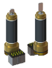
_ Laser entertainment (light show) displays
_ Optical Coherence Tomography
_ Optical Layout Templates
_ Raster Image Projection
_ Confocal Microscopy
_ Laser Marking
UNIQUE ScannerMAX FEATURES
_ Stronger magnetic field
_ Stronger rotor and shafts
_ Stronger, integrated back-supporting mirror mount
_ Stronger SV30/silicon dioxide ceramic hybrid bearings
_ Stronger position feedback with low noise
_ Cooler-running motor magnetic design
BENEFITS
_ Extremely high speed mirror positioning
_ Wide-angle scanning, up to 80 degrees optical
_ Convenient package size, compatible with many existing
X-Y mounts
_ Low coil resistance for low heat generation during
scanning
_ Low thermal resistance for enhanced heat removal
_ Low wobble and jitter
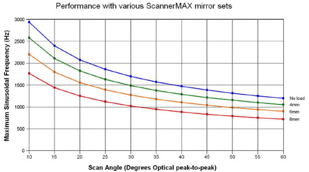
GENERAL DESCRIPTION
The Saturn 5 optical scanner is specifically designed to
meet the high acceleration and high RMS duty cycle demands of projection
and imaging applications such as laser entertainment displays, raster
imaging, Confocal Microscopy and Optical Coherence Tomography. The
Saturn 5 is capable of moving a 3mm beam through an optical angle of 30�
at a frequency of over 1,600 Hz with a sinusoidal drive. Step response
times can be as low as 100 microseconds for a 5� optical step and under
500 microseconds for an 80� optical step.
In addition to its high-speed capabilities, the Saturn 5
incorporates several very desirable design features. First, because of
its half-inch-round body dimensions, the Saturn 5 is easily retrofitable
into many existing systems. Second, the integral back-supporting mirror
mount virtually eliminates �diving board� bending-mode mirror resonances
while also easing field replacement of mirrors. And finally, the
high-output, low-noise position detector enhances short-term
repeatability and minimizes dither.
The newly-developed X3 magnetic circuit boasts air gap
flux densities of over 14,000 Gauss. The intense magnetic field
strength, combined with the very low coil resistance and low rotor
inertia, gives the Saturn 5 the highest peakand RMS-torque-to-inertia
ratio of any commercially-available optical scanner.
THE ScannerMAX ADVANTAGE
Instead of placing turns of copper wire in between the
steel and magnet, we bury our wire in slots within the steel, which
maximizes flux density. As a result, fewer turns of copper wire are
needed to create the same amount of torque, thus inductance is no
greater than in a standard galvanometer scanner. In addition, we use a
thicker cooper wire inside of our unique slotted design, which allows
our scanner to dissipate the heat better than current industry standard
galvanometer�s can. We combine this with a much stronger shaft, which is
3mm in diameter vs. the common 2mm in diameter, used by many of today�s
standard galvanometer�s and we position the mirror closer to the magnet.
The end result is a much stronger scanner, which can operate at cooler
temperatures, allowing our scanners to perform at much faster speeds.
OUTLINE DRAWING
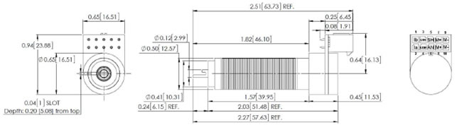
SPECIFICATIONS
|
Parameter |
Value |
Units |
|
Optimal Mirror Size |
3
-8 |
Millimeters, clear aperture |
|
Rotation Angle |
+/-20 |
Mechanical degrees |
|
Rotor Inertia |
0.028 |
Gram � Centimeters2 |
|
Torque Constant |
35000 (45775) |
Dyne � Centimeters per Ampere |
|
Maximum Rotor Temperature |
110
|
�C
|
|
Thermal Resistance (Rotor to Case) |
0.64 (0.69) |
�C
per Watt |
|
Coil Resistance |
1.0
(2.2) |
Ohms |
|
Coil Inductance |
95
(160) |
μh
|
|
Back EMF Voltage |
61.1 (79.9) |
μV
per degree per second |
|
RMS
Current |
8.4
(5.45) |
Amperes at Tcase of 50�C, Maximum |
|
Peak Current |
40
(25) |
Amperes, Maximum |
|
Small Angle Step Response |
100
(160) |
μS
with ScannerMAX 3mm mirror set |
|
PD
Linearity over 20 degrees |
99.8 |
%
Minimum |
|
PD
Linearity over 40 degrees |
99.4 |
%
Typical |
|
PD
Scale Drift |
50
|
PPM
/ �C, Maximum |
|
PD
Offset Drift |
15
|
μRad / �C, Maximum |
|
PD
Short-term Repeatability |
8
|
μRad |
|
PD
Output Signal (Common Mode) |
900
|
μA
with LED current of 60mA |
|
PD
Output Signal (Differential Mode) |
60
|
μA
per degree, with LED current of 60mA |
|
Mass |
36
|
Grams |
*
Specifications in parenthesis indicate Saturn 5 version AW-52, which
offers an alternative stator winding.
* Saturn 5
version AW-52 has a higher coil resistance and is easier to drive for
typical servo amplifiers.
Specifications are at a temperature of 25� C. All mechanical and
electrical specifications are +/-10%.
4. System Options
For more complete levels of system
integration and solutions, we also provide the following system
components and solutions:
5. Scanner Applications
Laser Materials
Processing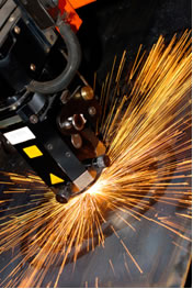
Laser material processing includes applications such as
laser marking, engraving, cutting, scribing, trimming, drilling and
welding. In these applications two galvanometer scanners are used in an
X-Y configuration to direct a high-intensity laser beam to a target
piece of material.
In the case of laser marking and engraving, the material
is often a plastic electronic part, such as an integrated circuit or
connector. In the case of laser cutting and scribing, the material is
often wood, metal or plastic, or even silicon such as integrated
circuits or photovoltaic solar cells. In the case of trimming, the
target material may be a resistive material on a resistor, whose
resistance is adjusted by removing material. In the case of drilling,
the material can be metal or even FR4 glass epoxy circuit board
material.
One of the most recent laser material processing
applications is textiles, such as blue-jeans. The laser projects
patterns onto the blue jeans material to give it an aged or worn
appearance, or to create unusual textures.
Laser material processing is generally not an application
which demands thermal performance from a galvanometer, but generally
does demand high bandwidth and low resonances.
Biomedical
Applications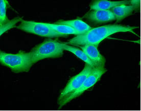
Biomedical applications include applications such as
Confocal Microscopy, Optical Coherence Tomography, Opthamology and
Dermatology. Like Laser Material Processing, these applications involve
two galvanometer scanners used in an X-Y configuration, but unlike laser
material processing, generally the laser beam is of a smaller size and
lower power level.
In the case of both Confocal Microscopy and Optical
Coherence Tomography, the X axis scanner is used to scan a fast,
sawtooth-like pattern while the Y-axis scanner is used to sweep the line
created by the X axis downward and upward across the tissue being
examined. This is essentially a raster-scanning application, but with
additional performance demands, since the X-axis scan often involves
beam power calibration on each scan. This application is particularly
demanding of the thermal performance of galvanometers because of the
heat generated by continuous high currents applied to create the X-axis
scanning motion.
In the case of Opthamology and Dermatology, these
applications are less demanding in terms of both heat and resonances,
because the motions are generally slower, smoother vector-oriented
motions. Generally dermatology is not at all a high-performance
application, but rather one that requires very light weight.
Laser image,
pattern and template projection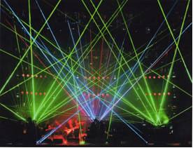
Laser projection applications include laser entertainment
(i.e. laser light shows), and Optical Layout Template (OLT)
applications.
Laser light shows have existed for more than 35 years, at
amusement parks, concert halls, night clubs and special events. Laser
light shows present some of the greatest demands to galvanometer
scanners because of the wide range of patterns projected over a range of
angles which are usually wide angles.
Optical Layout Templates involves using a laser
projection system to project a template pattern which is generally
originates as a CAD file. The projected pattern often serves as an aid
for humans who use the template to assemble large plies of material such
as roof trusses or multi-part aircraft wing structures. The projected
template can also act as a guide as to where leather or cloth will be
cut during a separate operation.
Often times both laser light show and OLT applications
present both thermal and resonance demands to a galvanometer system.

Stereo
lithography and other printing applications
Stereo lithography involves two separate X-Y galvanometer
scanning systems, each directing a laser beam to a target liquid-like
material. Where the beams meet, a chemical reaction is formed which
cures the material. Such formations happen layer by layer to create a
solid, three-dimensional part. The part can be used as a prototype, or
simply as a mock, to examine a prospective design before committing it
to a more permanent and expensive material.
Galvanometers can also be used along with other types of
scanners, such as resonant scanners or polygonal scanners, to create
raster-scan patterns for direct-to-plate or direct-to-film printing
applications.
Stereo lithography and printing applications are
generally demanding of the positioning repeatability capability of a
galvanometer scanner.
Image capture
Image capture involves using galvanometer scanners to
effectively position a camera on a target surface. This is unlike all of
the other applications mentioned above. Instead of a stationary laser
beam projecting light off of two galvanometer mirrors to reach a target
spot, a stationary camera is placed into the path of the two
galvanometer mirrors, which allows those mirrors to position the
camera�s view anywhere on the target surface.
Imaging applications are generally not very demanding of
a galvanometer, since this is most often a kind of �move and hold�
application.
As you can
see, there are a wide range of applications that are currently being
served very well by galvanometer scanners. We believe that there are
more applications that have yet to be discovered. Please contact us to
discuss your requirements. We will be happy to explore how galvanometer
scanners may help in your application.
|