|
Our marking
software has been designed to meet the needs of all types of users of
laser marking systems. The software was developed to be a retrofit
package for existing systems, or as original software on new systems.
The package provides significant advancements over previous laser
marking control systems, while remaining extremely user-friendly. It's
an object oriented, graphically interactive, PC control system providing
a user the ability define and execute laser marking jobs. Multiple
hardware interfaces are supported giving the software the ability to
control most Nd:YAG and CO2 laser
marking systems.
Unlike some
marking software, the operator never has to remember what fonts and
logo's need to be loaded for a particular job. The software
automatically performs all required graphic loading. The software does
not require users to learn any programming languages or special codes,
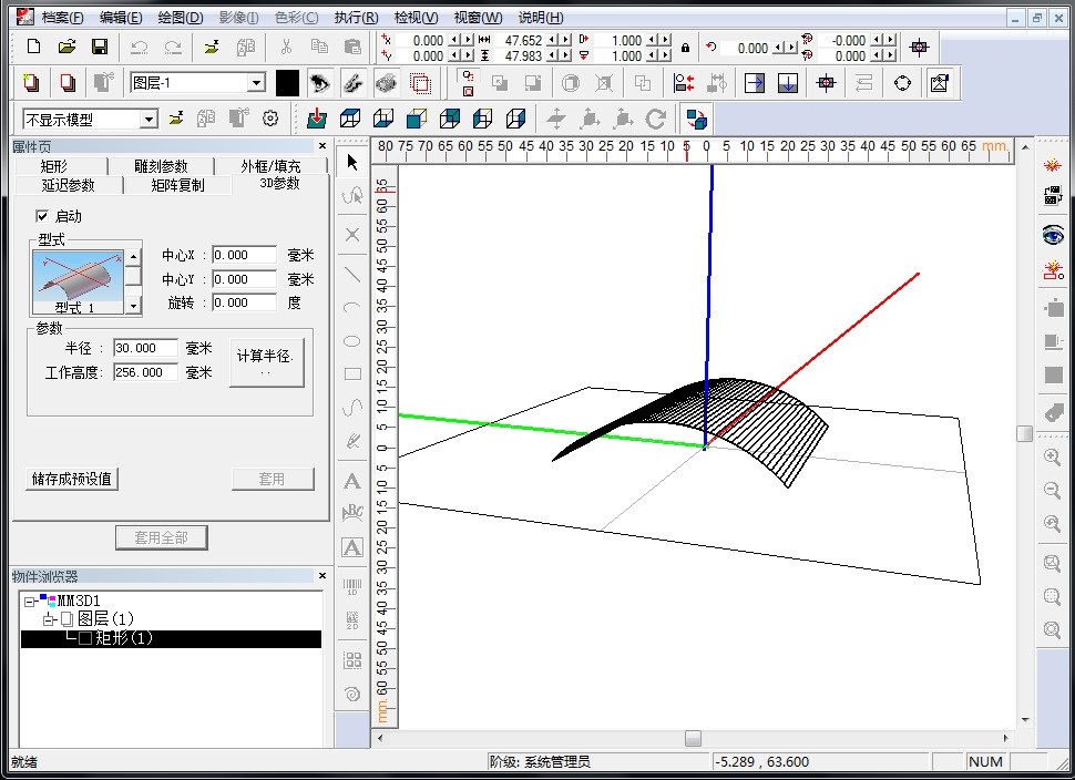
and yet the software provides all of the flexible, graphic control users
are accustomed to, including radial marking, aspect control, character
spacing, angular rotations, and full justification. Text to be marked
can be fixed or variable. Variable text can be retrieved at runtime from
a variety of sources including, the keyboard, a bar code reader, and
disk files. Automatic date coding and alphanumeric serialization are
included as variable text types. Fonts include laser engraving fonts and
Window�s True Type fonts. True Type fonts can be vector filled using
user specified density, angle and kerf. Graphics (sometimes called
"logo's" on other systems) can be imported from a large variety of
common vector formats. All graphic features are either menu controlled
or graphically controlled via the mouse and keyboard.
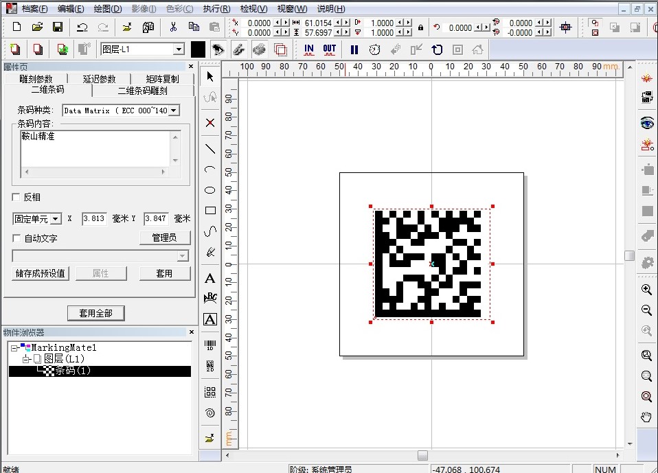
The
software can create various objects such as barcode, DataMatrix, text,
simple geometrical objects (such as line, rectangle, round-corner
rectangle, polygon, circle, ellipse etc), complex graphic objects (such
as PLT & BMP files), automatic date coding and alphanumeric
serialization.
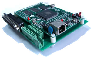
Digital card (control CO2 laser, YAG laser)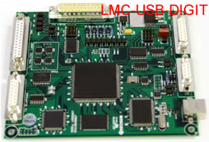
l
Data transfer:usb2.0 interface
l
Digital output used for scan head
l
Support FPK with three ways [optional]
l
Support high-speed fly marking with rotary encoder
l
Eight digital input and seven digital output used for
other controlled equipment
l
25 routes general digital signals(TTL compatible), 4 of
the IO ports can be OC IO, can connect with relay.
l
LASER Signal: TTL, used for laser On/Laser Off .
l
PWM Signal: TTL, used to adjust the frequency and duty
ratio.
l
Tow Direction/Pulse signals, used to control stepping
motor.
l
START Signal: used to connect foot switch
SPI G3.0 card (control SPI laser)
l
Use 68-pins SCSI 3 socket, connect SPI G3 laser module
via 68-pin cable directly
l
Adjustable digital/analog output used for scan head
l
Mark-on-fly function with an encoder connected
l
Extend axes output: Two Direction/pulse signals, used to
control stepping motor or servomotor
l
25 routes general digital signals(TTL compatible), 4 of
the IO ports can be OC IO, can connect with relay
l
Original start signal: Used when marking contents are the
same and high speed is required
l
Compatible with USB2.0
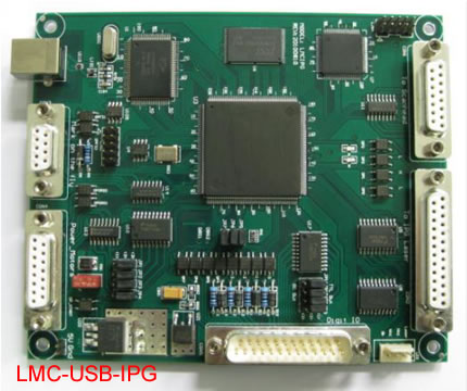
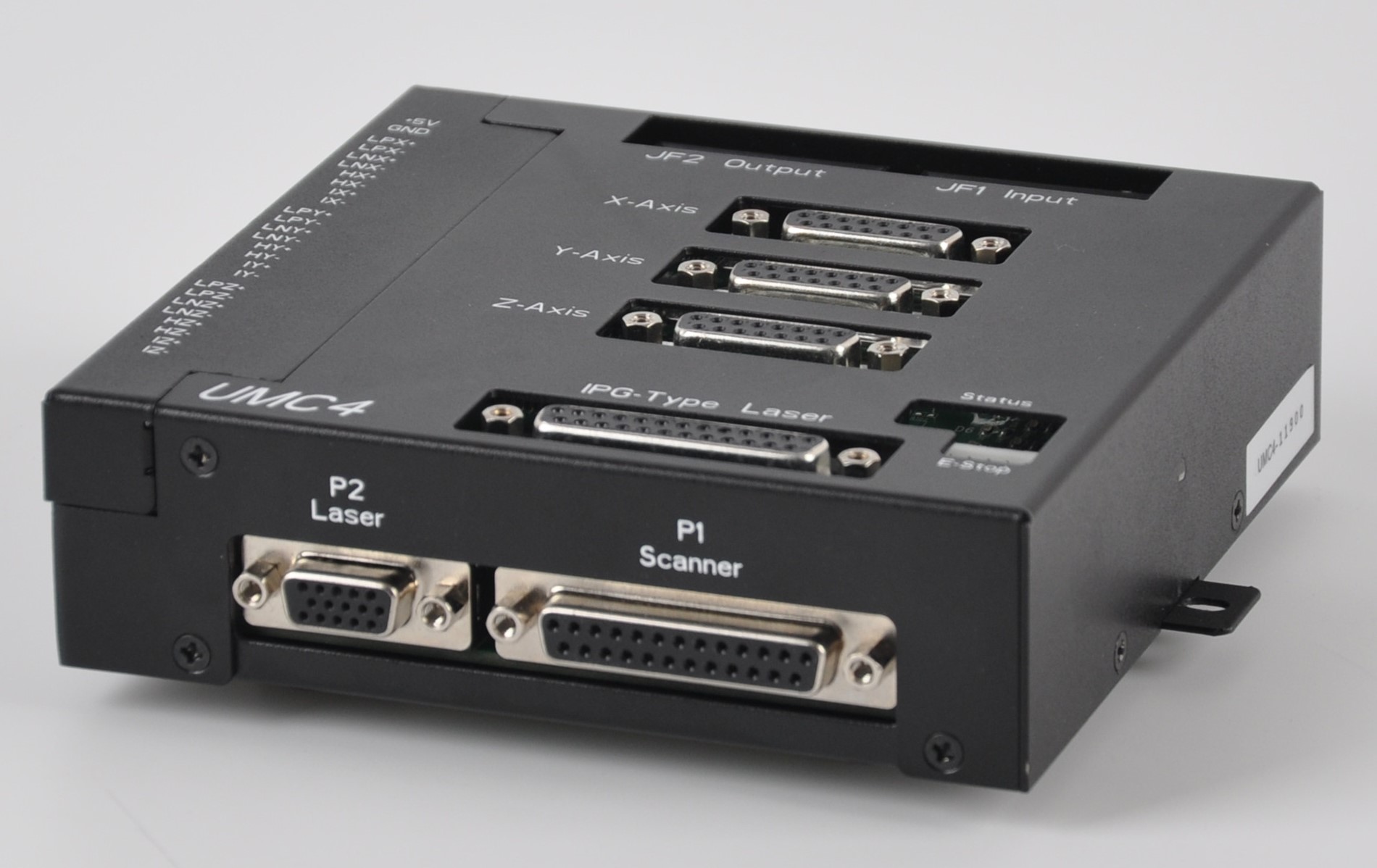
IPG CARD
(control
IPG-YLP laser and IPG-YLPM laser)
l
Use 25-pins DB25 socket, connect IPG YLP and YLPM laser
module via 25-pin cable directly
l
Adjustable digital/analog output used for scan head
l
Mark-on-fly function with an encoder connected
l
Extend axes output: Direction/pulse signals, used to
control stepping motor or servomotor
l
25 routes general digital signals(TTL compatible), 4 of
the IO ports can be OC IO, can connect with relay
l
Original start signal: used when marking contents are the
same and high speed is required.
l
Compatible with USB2.0
Dynamic focus board
l
Dynamic focus .three digital output for scan head
l
Support FPK with two ways (optional)
l
6 routes digital input and 6 routes digital output
l
LASER signal : TTL, used for laser on/laser off
l
PWM signal: TTL ,used to adjust the frequency and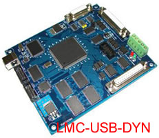 duty ratio
l
Direction/pulse signals ,used to control stepping motor
or servomotor
l
DB25 connector used for IPG YLP laser directly (optional)
l
Compatible with USB2.0
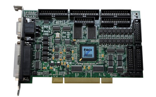
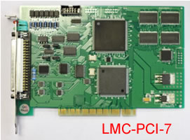
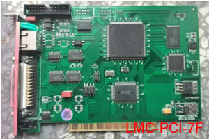
PCI Board (control CO2 and YAG laser)
PCI-7F board (control fiber laser)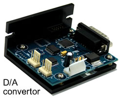
DA Converter Board
DA converter is an integrated product for digital to
analogue single conversion, to enable higher marking accuracy and long
distance signal transmission which is less susceptible to electrical
noise.
Model and description for LMC boards:
|
Model |
Main function |
|
LMC-PCI-7 |
2D marking to 2D analog galvos plus 2 axes
(rotary stage, on-fly, Z-axis or XY-axis) to control CO2 or YAG
laser. |
|
LMC-PCI-7F |
2D marking to 2D digital galvos plus 1 axis
(rotary stage or Z-axis) to control fiber laser. |
|
LMC-USB-DIGIT
|
Digital card, to control 2D digital galvos plus 2
axes (rotary stage, on-fly, Z-axis or XY-axis) to control CO2 or
YAG laser. |
|
LMC-USB-IPG |
Fiber digital card, to IPG fiber lasers, 2D
marking to control 2D digital galvos plus 2 axes (rotary stage,
on-fly, Z-axis or XY-axis) |
|
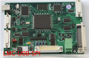
LMC-USB-SPI |
Fiber digital card, to SPI fiber lasers, 2D
marking to control 2D digital galvos plus 2 axes (rotary stage,
on-fly, Z-axis or XY-axis) |
|
LMC-D/A |
D/A conversion card, to convert 2 input digital
signals into 2 output analog signals , which are used to drive
analog galvos. |
Remark:
The boards always come with 2D marking to control 2D
galvos plus one axis (rotary or Z-axis). On-fly and XY-axis are
available upon request at additional cost.
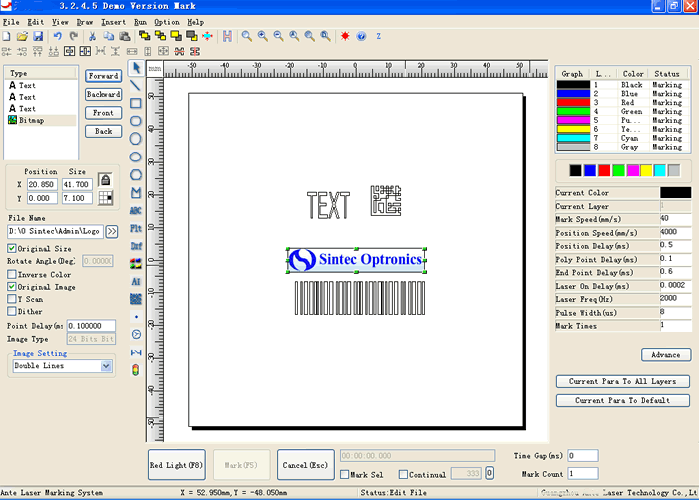
Its marking software is shown as follows:
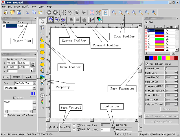 |

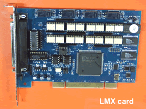 LMX Marking
Control Card is especially developed for scan head and laser control in
real time with a PCI bus interface. It is used with corresponding
software to control laser marking.
LMX Marking
Control Card is especially developed for scan head and laser control in
real time with a PCI bus interface. It is used with corresponding
software to control laser marking.