|
1.
ST-FFP
Series Far Field Profilometer Instrument
ST-FFP far field
measurement instrument is a stand-alone device for measuring light intensity vs
output angle of light emitting components such as high optical power laser diode
bars and other high intensity light sources.
Features
� Standard
input wavelength range 400-1700 nm
� Input
optical power up to 100W CW
� Scanning
angle range �90�
� Angular
resolution 0.03�
� High
dynamic range of >60 dB
� Noise
free measurement of pulsed light
� USB
connection, easy to use software
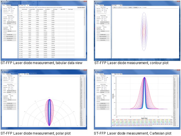
� Advanced
plotting features: 1D, 2D, 3D and contour plots
� Tabular
data displaying FWHM and NA
� Export
measurement data into various formats
� Fixtures
for FC, SMA fibers and various LEDs and lasers available
� Maintenance
free
Applications
� Light
emission intensity vs output angle analysis (a.k.a. far field)
� High
optical input power capability
� Numerical
aperture characterization of optical components
� Designed
for high power laser diodes
� Automated
laser diode quality assurance
� Suitable
for LED, laser diode, laser bar and fiber
Specifications:
|
Model |
ST-FFP-VIS-IR |
ST-FFP-RGB |
Customized |
|
Wavelength
range |
500 � 1700
nm |
Separate
R,G,B channels |
From 200 to
3000 nm |
|
Field of
view |
+/- 89� |
+/- 89� |
+/- 89� |
|
Light input
aperture |
30 mm or
SMA/FC fiber mount |
30 mm or
SMA/FC fiber mount |
1-50 mm,
custom shape |
|
Agnle
resolution |
0.03� |
0.03� |
0.03� |
|
Angle
resolution in 3D scans |
0.05� |
0.05� |
0.05� |
|
Azimuth
resolution |
0.01� |
0.01� |
0.01� |
|
Optical
input power |
50 �W �
100W |
50 �W �
100W |
10 �W �
200W |
|
Dynamic
range |
>60 dB |
>60 dB |
Up to 90 dB |
|
Sampling
time |
1.3 � 1000
ms |
1.3 � 1000
ms |
1 �s � 1 h |
|
Scanning
speed |
0.05 � 300
�/s |
0.05 � 300
�/s |
0.05 � 300
�/s |
|
Photodiode
sensitivity ranges |
5 decades |
5 decades |
5 decades |
|
PC
conncetion |
USB |
USB |
USB or
custom |
|
Programming
interface |
ASCII text
commands through virtual COM port, optional C# library with examples |
ASCII text
commands through virtual COM port, optional C# library with examples |
Standard or
customized |
|
Power |
12 V DC 1.5
A |
12 V DC 1.5
A |
12 V DC 1.5
A |
|
Dimension
|
305x331x335mm |
305x331x335mm |
305x331x335mm |
|
Weight
|
10kg |
10kg |
10kg |
|
Approvals |
CE |
CE |
CE |
|
Software
operating system |
Windows
2000 or later,
32 or 64
bit OS |
Windows
2000 or later,
32 or 64
bit OS |
Windows
2000 or later,
32 or 64
bit OS |
|
Data
display |
Cartesian,
polar, 3D, contour, table |
Cartesian,
polar, 3D, contour, table |
Cartesian,
polar, 3D, contour, table |
|
Export
formats |
CSV, PDF,
PNG, PS, XML |
CSV, PDF,
PNG, PS, XML |
CSV, PDF,
PNG, PS, XML |
Capabilities
2.
ST-LDC
Series Automated Laser Diode/Bar Characterization & Testing Systems
ST-LDC systems are
fully configurable, all-in-one laser diode and LED characterization devices for
industries and R&D laboratories. They�re designed to measure and analyze all
major characteristics of laser diodes and LEDs in a fast and reproducible way.
They�re ideal tool for data sheet generation, quality control, failure analysis
and research activities with semiconductor emitters.
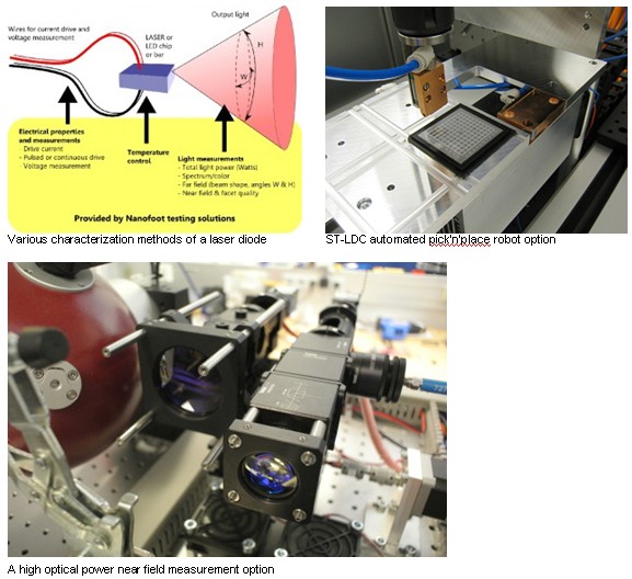
ST-LDC systems are
customizable tool to meet various needs required by different activities. They
can measure devices from UV-LEDs to telecom laser diodes and high power laser
bars, we can features a camera assisted pick�n'place robot capable of collecting
diodes from customer supplied trays and finally marking and sorting them after
the tests.
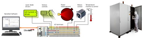
Architecture
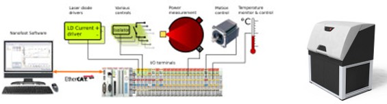
ST-LDC systems are
having modular construction based on robust field bus technology. This
construction makes high scalability and easy maintenance possible while keeping
number of components minimum.
On ST-LDC system
without pick�n'place robotics, devices under test (DUTs) are loaded into the
system on multichannel
load-trays
that are equipped with an individual low resistance bypass switch over each DUT
to allow series connected devices operating even in case of open circuit or
empty slots. Load tray also features channel specific temperature and voltage
monitors and optionally a channel specific temperature control.
ST-LDC capabilities
|
|
Value |
Remarks |
|
DUT type |
Laser
diode, Laser bar, LED, HB LED, UHB LED |
Multiple
DUT adapters are possible with single ST-LDC |
|
DUT current
driver |
> 0-500 mA
(CW and/or pulsed)
> 0-5 A (CW
and/or pulsed)
> 0-20A (CW
and/or pulsed)
> 0-60A (CW
and/or pulsed)
> 0-120A
(CW and/or pulsed)
> 0-200A
(pulsed only)
> 0-400A
(pulsed only) |
Multiple
drivers are possible within single ST-LDC |
|
Load-tray support |
Yes |
|
|
Power
measurement (LIV) |
0-200 W
optical, 300 � 3000 nm |
Various
accuracy and calibration options available |
|
Spectrum
measurement |
200 � 2400
nm, resolution from 10 pm to 1 nm |
Based on
OSA or spectrometer |
|
Far field
measurement |
See ST-FFP
specifications |
|
|
Visual
ispection |
Near field
integrity test |
Available
as low and high power type |
|
DUT
operating condition control |
> TEC/peltier
based, up to 30W cooling capacity per DUT, fast temperature variation
possible
> Water
cooled, up to 400W cooling capacity
per DUT
> Nitrogen
atmosphere optional
> Humidity
control optional |
Microchannel DUT support only with water cooling |
|
By-emitter
measurements |
Spectrum,
LIV, Polarity |
Only laser
for diode bars |
|
Throughput |
Depends on
the ordered options, contact us to receive throughput calculations |
|
|
Dimensions |
1200 x 900
x 1500 mm |
|
|
Weight |
200 kg |
|
|
Power |
220-240 V
AC 5 A |
|
|
Approvals |
CE |
|
ST- LDCrobo
additional capabilities
|
|
Value |
Remarks |
|
DUT type |
Laser
diode, Laser bar, LED, HB LED, UHB LED |
Multiple
DUT adapters are possible with single ST-LDC |
|
Functions |
> Locate
and measure chip position
> Pick chip
> Align and
place on testing bench
>
Optionally mark chip
> Place
chip: Back to the original tray, Sort to different trays, Discard |
|
|
Machine
vision alignment |
Included |
|
|
Throughput
(standard model) |
Up to 3 DUT
per minute |
Time varies
by the tests to be performed, contact us for calculation |
|
Throughput
(high volume model) |
Up to 10
DUT per minute |
Tailor made
system for specific testing needs, contact us for calculation |
|
Bare chip
handling |
Yes |
DUT�s
supplied in a Gel-pak� |
|
Mounted
chip handling |
Yes |
Customer
specific DUT trays |
|
Available
accuracy grades |
> Basic:
+/- 20 �m
> High: +/-
10 �m
> Extreme:
+/- 1.25 �m |
|
|
Dimensions |
1200 x 900
x 1500 mm |
|
|
Weight |
200 kg |
|
|
Power |
220-240 V
AC 5 A |
|
|
Approvals |
CE |
|
Software:
|
|
Value |
Remarks |
|
Operating
software |
Measuretool |
|
|
Result
viewer & analysis tool |
Result
browser |
|
|
Common
Measurement Database (CMDB) |
Yes |
|
|
Operating
system |
Windows 7
32 bit |
Supplied
within LDC computer (included) |
|
Optical
Data analysis
|
Ith, Slope
Efficiency, Wall plug efficiency |
|
|
Electrical |
Rs, Vbias |
|
|
Thermal |
T0, T1 |
|
|
Spectrum |
dλ/dT, SMSR,
peak λ, FWHM |
|
|
Far field |
FWHM, Beam
Steering |
|
Capabilities:
3.
ST-BLT & ST-BLTnano Series Laser Diode Burn-in & Life-time Testers
ST-BLT
series burn-in testers are designed for laser diode manufacturing industry.
Stand alone ST-BLT test stations are optimal for high power laser diode burn-in
testing and quality assurance. Unique characterization features of ST-BLT
testers make them also suitable for simultaneous laser diode characterization
and data sheet generation. Each ST-BLT system is assembled to meet customer�s
specifications on laser bar optical power, mechanical dimensions, measurement
features and throughput.
A typical ST-BLT
system consist simultaneous burn-in station for 10 to 50 high power laser diodes
or bars each emitting up to 150 W of optical power. A system uses shared
measurement instruments and laser diode temperature controller for all laser
bars making it very cost effective
solution when
compared to competing systems.
ST-BLT
systems have modular construction based on robust field bus technology. This
construction makes high scalability and easy maintenance possible while keeping
number of components minimum. Multiple ST-BLT systems can be operated from a
single control computer. Devices under test (DUTs) are loaded into the system on
multichannel
load-trays
that are equipped with an individual low resistance bypass switch over each DUT
to allow series connected devices operating even in case of open circuit or
empty slots. Load tray also features channel specific temperature and voltage
monitors and optionally a channel specific temperature control.
ST-BLT
specifications,
on-line measurement model
|
|
Value |
Remarks |
|
Product
name |
ST-BLT |
|
|
Scalability |
1-64 ST-BLT
cabinets per one system |
|
|
DUT types |
Laser
diode, Laser bar, HB LED |
|
|
Load-tray support |
Yes |
|
|
On-line
measurements |
LIV,
Spectrum, Temperature |
|
|
Measurement
cycle |
User
definable |
|
|
Current
drive |
Up to 200 A
CW or pulsed, up to 20 kW per cabinet |
|
|
Temperature
control |
Water
cooling with chiller
TEC/peltier
with individual DUT temperature setting |
|
|
Safety &
DUT fault detection |
E-stop,
Over-temperature, Smoke detector, Short circuits, Open circuits, Optical
property change |
|
|
Dimensions
(W x H x D) |
700 x 1800
x 1200 mm |
Typical |
|
Power |
3 phase AC
380 VAC |
|
ST-BLTnano,
blind, non-characterizing type
|
|
Value |
Remarks |
|
Product
name |
ST-BLTnano |
|
|
Scalability |
1-64
BLTnano cabinets per one system |
|
|
DUT types |
Laser
diode, Laser bar, LED, HB LED |
|
|
Load-tray support |
Yes |
|
|
On-line
measurements |
Voltage,
Temperature |
|
|
Measurement
cycle |
Continuous |
|
|
Current
drive |
Up to 100 A
CW or pulsed / up to 1 kW |
|
|
Temperature
control |
Water
cooling with chiller |
|
|
Safety &
DUT fault detection |
E-stop,
Over-temperature, Smoke detector, Short circuits, Open circuits |
|
|
Dimensions
(W x H x D) |
700 x 500
210 mm |
Typical |
|
Power |
1 phase 230
VAC |
|
4.
ST-VIS Series Visual Inspection System
ST-VIS is dedicated
tool for laser bar inspection in production environment. This system inspects
around 50 laser bars in hour for any visible defects in (sub threshold) near
field or at surface of exit facet. While doing this system provides also
accurate measurement from laser bar overhang and smile.
ST-VIS classifies
all images and measurement results to passed / failed by internal criteria /
failed by external criteria. These rulings may be used to see which bars can be
sold, when bars can be sold although they have some defects and when bars are
too defective to be sold. ST-VIS also provides systematic way to find defects.
For example result stored to database can be: Emitter 18 had too large defect,
and its overhang was too big (22.1 �m).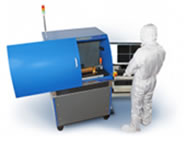
Features:
� ST-VIS
replaces operator in labour intensive facet inspection and provides key
advantages
� Defects
are found every day � every hour. System does not have bad days and it does not
get tired.
� Simultaneous
near field inspection provides enhanced way to find faulty devices
� All
results are systematically logged and easily accessible afterwards.
Facet and
Near-Field inspection
The facet
inspection option can be used to detect particles, cracks and coating defects
down to 1 �m in diameter. With this option a microscope is used to take an image
from front facet which can be analyzed either by the user or by machine vision
software.
We have developed
measurement modes that work in conjugation with facet inspection using same
camera and opto-mechanics. These new measurement options are sub-threshold NF
imaging and overhang measurement. Sub threshold imaging of NF helps system to
find defects that are difficult to find using regular machine vision imaging
methods. This option provides enhanced defect detection. With this mode facet
inspection (NF and visual) and overhang measurement can be done in less than 75
s per bar (19 visual inspection images, 19 NF images and overhang measurement).
This enables inspection of more than 300 laser bars per day.
Overhang
measurement
Second new mode,
overhang measurement, allows system to use focus data from laser diode facet and
from submount to determine overhang of laser bar. Overhang of the bar is
measured from both edges of bar and for single emitters measurement is done at
the centre. This verification is important in order to qualify bar mounting
process.
Smile
measurement
High precision
smile measurement entity. Contains high resolution low distortion microscope and
enhanced vibration isolation. This can be used to measure laser bars smile with
+/- 0.2 �m accuracy (95% of confidence). Although system is vibration isolated,
due to extreme accuracy of measurement, system must be installed in space
without excessive noise and vibrations to reach specified accuracy.
Configurations:
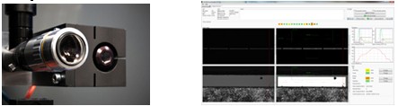
ST-VIS
cameras ST-VIS result studio
Specifications:
|
Property |
Value |
Remarks |
|
DUT�s per
Load tray |
8,16 or 24 |
|
|
Throughput |
0.5-2 DUTs/min |
For 19-47
emitter bars |
|
Particle
regognition |
1 �m |
|
|
Near-field
continuity check |
Yes |
|
|
Smile
measurement resolution |
100 nm |
|
|
Smile
measurement repeatability |
+/- 250 nm |
Typical |
|
Overhang
resolution |
100 nm |
|
|
Overhang
repeatability |
+/-1�m |
Typical |
|
Near-field
laser drive current |
0.1-100 mA |
Auto-adjusting |
|
SQL
database support |
Yes |
|
|
Offline
results browser |
Yes |
|
|
Dimensions |
1200 x 750
x 1500 mm |
|
|
Weight |
220 kg |
|
|
Power |
230 VAC,
5A, 1-phase |
|
|
Agencies |
CE |
|
Capabilities:
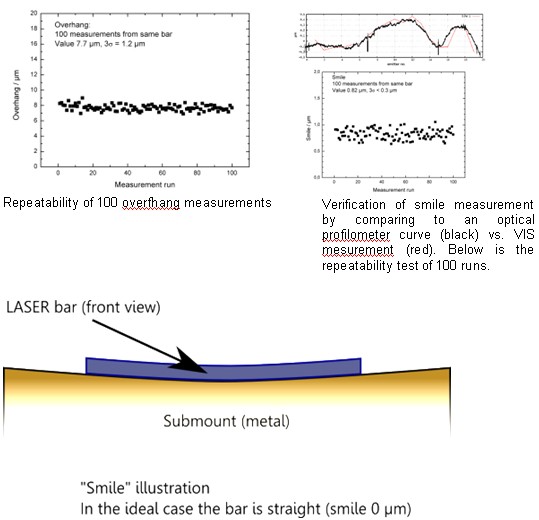
Repeatability of
100 overfhang measurements
 Optical fiber analyzer Optical fiber analyzer |