|
New Products |
|
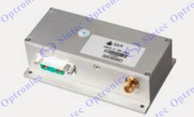
RF Driver |
|
|
|
|
|
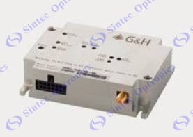 An
RF driver generates a fixed or variable frequency signal supplied to the
acousto-optic device�s transducer. This in turn uses the piezoelectric
effect to very precisely convert the RF signal to an acoustic wave that
propagates within the acousto-optic device�s crystal. The frequency and
intensity of the applied signal will determine how much an optical beam
is modulated, deflected, or tuned. An
RF driver generates a fixed or variable frequency signal supplied to the
acousto-optic device�s transducer. This in turn uses the piezoelectric
effect to very precisely convert the RF signal to an acoustic wave that
propagates within the acousto-optic device�s crystal. The frequency and
intensity of the applied signal will determine how much an optical beam
is modulated, deflected, or tuned.
An acousto-optic device and its RF driver should be selected as a unit
to optimize speed and stability for each application. Additional driver
features include first pulse suppression, synchronization, pulse
shaping, and multichannel operation. We offer a wide variety of stable
high frequency drivers with analog and digital modulation capability.
Voltage controlled oscillators (VCOs) vary the oscillation frequency via
the input voltage, and are a costeffective solution for applications
with less stringent frequency stability and linearity requirements.
Direct digital synthesizer (DDS) drivers offer higher stability, with
fast switching time and high resolution. They can create random
waveforms from a single, fixed-frequency reference clock, and thus are
ideal for pulse shaping and special functions. They also allow frequency
to be varied on the order of a few hundred nanoseconds, and are
inherently very linear. DDS drivers are software driven, and can be run
from a user-friendly interface (a GUI), or controlled directly via
computer driver commands. Our high-performance multi-frequency DDS
drivers generate up to 8 channels of RF frequencies simultaneously. |
|
|
|
Our standard models are below:
|
Model |
Compatible Devices |
Operating Frequency |
RF Power |
Key Features |
|
64020-250-1ADMDFS-A |
Beam deflector, special AOM, tunable
filter |
20-250 MHz
|
1.0 W |
Variable frequency; module |
|
64020-200-2ADMDFS-A |
Beam deflector, special AOM,
tunable filter |
20-200 MHz |
2.0 W |
Variable frequency; module |
|
97-02925-32 |
Beam deflector, tunable filter
|
20- 160 MHz |
0.4 W |
Single channel DDS; module |
|
97-03926-12 |
Beam deflector, tunable filter
|
20-160 MHz |
3.2 W |
8 channel DDS; module |
|
SD020-200-5UC- |
4x1 Tunable filter |
20-200 MHz |
5.0 W |
DDS module, single or multichannel |
|
A35xxx-S-1/50-p4k7u |
Fiber-Q, modulator |
40, 80, 110, 150, 200, 300 MHz |
5.0 W |
Analog/digital; module |
|
MHPXXX-YYADMA1
|
Fiber-Q, modulator |
24-260 MHz |
2-20 W |
Analog/digital; module |
|
1xxxAF-xIN0-x.xHCR |
Fiber-Q, modulator, frequency
shifter |
80-350 MHz |
0.5-4.0 W |
Analog/digital; module |
|
HP041-125ADGA10 |
Modulator |
40.68 MHz |
125 W |
Analog/digital; module |
|
HP040-060-150ADG-A10-2X |
Modulator |
40/60 MHz |
2x75 W |
Dual frequency; analog/ digital;
module |
|
MQH0XX-YYDMZZZ |
Q-switch, modulator |
24, 27.12, 40.68, 68, 80 MHz |
25-100 W
|
Analog/digital; module |
|
MQH0XX-YYDM-ZZZ-2S |
Q-switch |
24, 27.12, 40.68, 68, 80
MHz |
25-50 W
per channel |
2 channel Analog/digital; module |
|
QC0XX-YYDC-ZZZ-AAV |
Q-switch, modulator |
24, 27.12, 40.68, 68, 80,
110 MHz |
2-24 W |
Analog/digital; module |
|
|
|
|
Old RF Driver models below: |
| Old RF Driver models below: |
N31xxx-yyAM
N31xxx-yyDM |
MLPxxx-yAC
MLPxxx-yAS
MLPxxx-yDC
MLPxxx-yDS
(N21xxx-yAM N21xxx-yDM) |
1xxxAF-AINA-y HCR
1xxxAF-DINA-y HCR
(A35xxx-S-1/50-p4k7u) |
A36xxx |
| RF power |
2-20W |
0.4, 1 or 2W |
0~5W (Analogue) |
2W |
| RF frequency, MHz |
24-260 |
27-300 |
80,
100, 110, 150, 200, 250, 300, 350 |
| Max. modulation frequency |
|
<1/3
carrier frequency and <50MHz |
| Input modulation |
Analogue or digital |
Analogue and digital |
|
|
|
|
Description
of N series drivers:
xxx
= a fixed frequency of between 27 and 300 MHz crystal controlled.
y
= 0.4, 1, or 2 Watts output (N21 series), 2-20W adjustable output (N31
series)
D = Digital Modulation or A =
Analogue Modulation
M = OEM Module
|
|
|
|
Description
of A3 series drivers:
♦ low
profile housing
♦ various
standard frequencies, other frequencies from 40 to 350 MHz available
♦ analogue
and digital modulation
♦ EMC-safe
design, power stage and control circuits separately grounded, entirely
shielded
♦ supply
voltage 24 V DC |
 |
Connector cable for A35xxx and A36xxx AOM
drivers.
This accessory provides the connection of the analogue and digital
modulations interface as well as the power connection for the A35xxx and
A36xxx AOM driver series. It comprises the fully shield plug and 1 meter
pigtails. The RF connecting cable between the RF driver and the AOM is
not included. Ordering Code : 508A00169 |
|
|
|
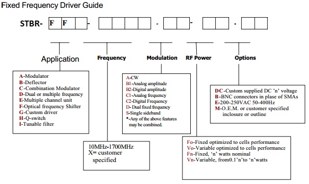
RF Drivers for STBR Series |
|
FF Series typical fixed frequency RF drivers
configurations:
| Model |
STBR-FF-XX-B1-FY |
STBR-FF-XX-B2-FY |
STBR-FF-XX-B3-FY |
| Output Frequency |
XX
MHz (compatible with the AO device) |
| Frequency control |
Quartz crystal referenced phase locked loop |
| Frequency Accuracy |
0.015 |
| Harmonic Content (dBc) |
<=-20 |
| Frequency Stability |
0.0015% minimum after 15 minute warmup |
| Output power |
Power
is optimised for peak efficiency with supplied AO device |
| Output protection |
Power
amplifiers used will tolerate an infinite VSWR without damage.
Rated power is available only when a proper RF load is connected |
| Internal Pulse
Generator |
|
N/A
|
Pulse
width: 100 to 500 nsec � 10% adjustable, pulse generator with
5000 Hz to 100 KHz rep rate adjustable. Front panel switch for
pulse/standby operation. |
| Rise/Fall Time |
To
match AOM requirements |
| Modulation Type |
Analog amplitude modulation
|
TTL
compatible
|
Pulse
modulation, pulse monitor output via front panel BNC connector |
| Modulation Rate |
To
match device requirements |
| Modulation Input |
50
ohml 0-1V
|
330ohm; 0-5V
|
Internal or external trigger |
| Operating Power |
90-250 VAC, 50-60Hz, 55 W max |
| Enclosure |
The
unit will be packaged in a 190mm (7.5inch) wide by 90mm (4inch)
high by 220,, (8,75inch) deep instrument case. The rear panel
heat sink increases the depth to 240mm(9.75inches) maximum. The
size is exclusive of connectors |
| Environmental |
Nominal Lab conditions: Max temperature is +35 degC. The unit is
not seals against moisture or condensing humidity |
|
|
|
 |
|
|
|
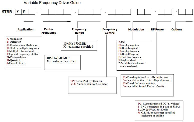
VF Series typical fixed frequency RF drivers configurations:
| Model |
STBR-VFB-XX-YY-V-A-F2 |
STBR-VFE-XX-YY-V-A-F2 |
| Output Frequency
Range |
Corresponding to AO Device Requirements |
Matching the 2-D AOD controlled by application of external
tuning voltage |
| Tuning Voltage |
0 -
10 V analog (-2 to +20 VDC no damage) |
| Frequency Accuracy |
1%
nominal after 15 minute warm-up, constant temperature |
| Scanning speed |
50
micro sec from min to max frequency with step change in tuning
voltage |
| Output power |
Power
is optimised for peak efficiency with supplied AO device |
| Modulation Type |
Analog amplitude or TTL compatible (optional) |
Analog Amplitude; DC-10MHz independent for each channel |
| Modulation Input |
50
ohm; 0-1V OR 330ohm; 0-5V
|
50
ohm; 0-1V |
| Operating Power |
90-240 VAC, +-25%, 50-60Hz |
| Enclosure |
The
unit will be packaged in a 190mm (7.5inch) wide by 90mm (4inch)
high by 220,, (8,75inch) deep instrument case. The rear panel
heat sink increases the depth to 240mm(9.75inches) maximum. The
size is exclusive of connectors |
| Environmental |
Nominal Lab conditions: Max temperature is +35 degC. The unit is
not seals against moisture or condensing humidity |
|
|
|
 |
|
|
|
|
|
Fiber-Q RF Driver |
 Each
Fiber-Q acousto-optic modulator requires an RF driver to control the
embedded acousto-optic crystal, as modulation of the beam depends upon
the frequency and intensity of the applied RF signal. Each
Fiber-Q acousto-optic modulator requires an RF driver to control the
embedded acousto-optic crystal, as modulation of the beam depends upon
the frequency and intensity of the applied RF signal.
The RF signal which generates the acousto-optic wave in the
acousto-optic crystal can do so very precisely at a fixed or variable
frequency, and is created using a transducer mated to the acousto-optic
crystal and driven by the piezoelectric effect.
Analog, digital, and combined RF drivers are available for use with the
Fiber-Q series. All are designed for dependable stability and high
frequency operation, with compatible options for the full line of
visible and NIR Fiber-Q products. The speed and stability of a modulator
is limited by the stability and speed of the RF driver, and thus the two
should be selected as a paired unit to optimize performance, features,
and application-specific options.
The primary factors to consider when selecting an RF driver include the
operating frequency, the required rise/fall time of the application, and
whether analog or digital modulation is needed. RF power, duty cycle,
stability, and variable vs fixed frequency are also relevant.
Drivers for the Fiber-Q series of modulators are designed for constant
RF power output, fast modulation, and with conductive cooling via the
baseplate. When tuned together with the modulator, they offer stable,
dependable modulation to enable all-fiber laser systems. |
| Model |
Operating Frequency |
RF Power |
Key Features |
| 97-09210-18 |
80 MHz |
3.0 W |
Analog |
| 97-09210-19 |
80 MHz |
3.0 W |
Digital |
| A35080 |
80 MHz |
3.0 W |
Analog/digital |
| A35110 |
110 MHz |
3.0 W |
Analog/digital |
| 97-09210-14 |
150 MHz |
2.5 W |
Analog |
| 97-09210-15 |
150 MHz |
2.5 W |
Digital |
| A35150 |
150 MHz |
2.5 W |
Analog/digital |
| 97-02910-04 |
200 MHz |
2.5 W |
Analog |
| 97-02910-01 |
200 MHz |
2.5 W |
Digital |
| A35200 |
200 MHz |
2.5 W |
Analog/digital |
|
|
|
 N21xxx-yAM
N21xxx-yDM
N31xxx-yADM A36xxx
AOMs N21xxx-yAM
N21xxx-yDM
N31xxx-yADM A36xxx
AOMs |
|
|